Titanium’s low thermal conductivity (6.7 W/m·K — roughly 1/8 of steel) traps cutting heat at the tool tip instead of dissipating it into the workpiece. That concentrated heat, combined with titanium’s HCP crystal structure, causes work hardening when feed rate drops too low or the drill dwells. The fix is counterintuitive: keep speeds conservative (50–230 SFM depending on alloy and tool material) but keep feeds aggressive enough that the drill is always cutting, never rubbing. This guide provides alloy-specific drilling parameters, drill geometry specifications with coating guidance, coolant pressure requirements, peck drilling strategy, and a troubleshooting table — all sourced from Carpenter Technology, Kennametal, Sandvik, Guhring, and peer-reviewed manufacturing research.
Why Titanium Is One of the Hardest Metals to Drill
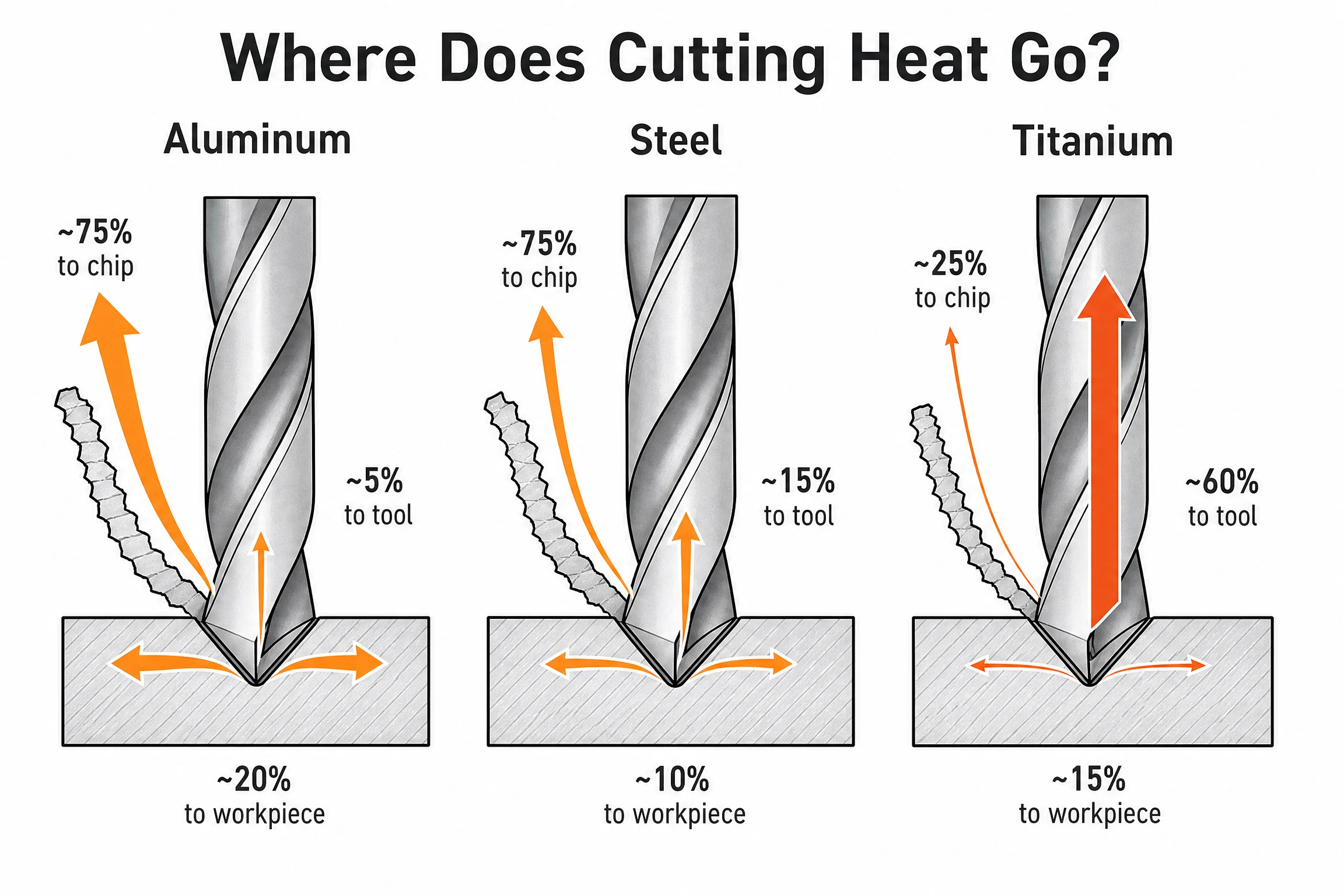
The challenge with titanium drilling comes down to one number: 6.7 W/m·K. That’s the thermal conductivity of Ti-6Al-4V, the workhorse aerospace alloy. For context, carbon steel conducts heat at roughly 50 W/m·K, and aluminum 6061-T6 at 167 W/m·K.
When you drill aluminum, the majority of heat generated at the cutting edge flows into the chip and workpiece. When you drill titanium, that ratio shifts dramatically. Research compiled at Kansas State University, drawing on multiple drilling studies, found that roughly 60% or more of the heat generated in titanium drilling is absorbed by the cutting tool — compared to approximately 15% in steel drilling. The chip carries heat away very slowly; the workpiece absorbs almost none. Everything concentrates at the tool-chip-workpiece interface.
The consequence is predictable: even at moderate cutting speeds, interface temperatures in Ti-6Al-4V drilling can exceed 900°C (IntechOpen, Chapter 32761 — a peer-reviewed summary of titanium drilling machinability research). At those temperatures, three bad things happen simultaneously:
- Diffusion wear — Titanium atoms migrate into the cobalt binder of your WC-Co carbide, dissolving the binding matrix at the cutting edge.
- Built-up edge (BUE) — Titanium, which has a strong chemical affinity for many tool materials, begins welding itself to the cutting edge. When that material pulls away, it takes edge material with it.
- Work hardening of the near-surface layer — The extreme thermal stress in the material just below the cutting edge causes the HCP crystal structure of titanium to work-harden.
That third mechanism needs more explanation, because it’s the one that catches machinists off guard.
Titanium’s alpha phase has a hexagonal close-packed (HCP) crystal structure. Unlike FCC metals (aluminum, copper) or BCC metals (most steels), HCP has fewer active slip systems — the crystallographic planes along which dislocations can move to relieve stress. When the cutting edge plastically deforms the near-surface material, those dislocations pile up rather than sliding freely, progressively hardening the surface layer. The harder that layer becomes, the more force is required to cut it — which generates more heat, which makes it harden further.
The practical result: titanium drills that dwell, rub, or run at insufficient feed rate create a progressively harder zone at the bottom of the hole, and subsequent passes cut an increasingly hard surface. Drills break. Holes come out oversized. Reamers chatter.
None of this is inevitable. It’s entirely a function of how you cut.
Work Hardening in Titanium Drilling: Cause, Detection, and Prevention

Work hardening in titanium is not a material defect — it’s a process outcome. Every machinist I’ve talked to who struggles with it is doing at least one of three things wrong: running too slow a feed, using a G83 peck cycle without zeroing the dwell, or letting a worn drill stay in the cut too long.
The Three Causes
Cause 1: Insufficient feed rate (rubbing instead of cutting)
Every drill has a minimum chip load below which the cutting edge stops cutting and starts rubbing. In titanium, that rubbing generates heat without removing material — exactly the conditions for surface hardening. The Carpenter Technology machining guide for commercially pure titanium states it plainly: “It is important to avoid having the drill ride the titanium surface since the resultant work hardening makes it difficult to reestablish the cut.”
This is why the standard advice “go slow” only applies to cutting speed — not to feed. Feed rate must stay high enough to ensure the cutting edge is always engaging fresh material, not burnishing the previous pass.
Cause 2: Dwell at the bottom of peck cycles
Standard CNC peck drilling cycles (G83 in most control dialects) include an optional dwell parameter (P-word) that pauses the tool at the bottom of each peck before retracting. That pause is catastrophic in titanium. At zero feed rate, the spinning drill contacts the hole floor for however long the dwell runs — frictional rubbing, no chip, all heat. When the next peck engages, it’s cutting a hardened surface.
The fix is zero dwell on G83 (set P=0 or omit the P-word) or switch to a chip-breaking cycle (G73 on most Fanuc-compatible controls) that performs a short retract rather than a full-clearance retract. More on this in the peck drilling section.
Cause 3: Tool wear beyond the useful life
A dull cutting edge deflects and rubs before it cuts. The moment flank wear exceeds approximately 0.3 mm (the commonly cited tool change threshold for titanium), the drill is creating more heat than it removes with each revolution. Most shops find this out the hard way: the first 40 holes are fine, the last 10 are work-hardened and oversized.
How to Detect Work Hardening
You don’t need a hardness tester to recognize work hardening in progress. Observable symptoms at the machine:
- Sudden increase in spindle load mid-hole on the same workpiece — the drill is cutting harder material than it entered
- Drill discoloration — a blue-gold heat tint on the drill flutes suggests heat accumulation that will cause work hardening next cycle
- Oversized holes — thermal expansion of a heat-saturated drill combined with a harder bore wall pushes diameter above nominal. The academic study by Celik (2014, Materials and Technology) documented this consistently across all HSS drill configurations in Ti-6Al-4V.
- Reamer chatters or binds — if a reamed hole gives you chatter on a finish pass, the drilled bore is likely work-hardened
- Tapping torque spikes — work-hardened titanium requires significantly more torque to thread
Prevention: The Three Rules
- Keep feed aggressive enough to generate chips, not dust or powder — chips should be short and curled, not powdery (powder indicates rubbing)
- Eliminate all dwell time at the drill tip — in the peck cycle, in tool changes, and especially avoid stopping the spindle with the drill in contact with titanium
- Change the drill before it gets dull — in titanium, a drill worn to 0.3 mm flank wear is close to causing work hardening. Shorter tool life intervals prevent this.
Titanium Drilling Speeds and Feeds by Alloy
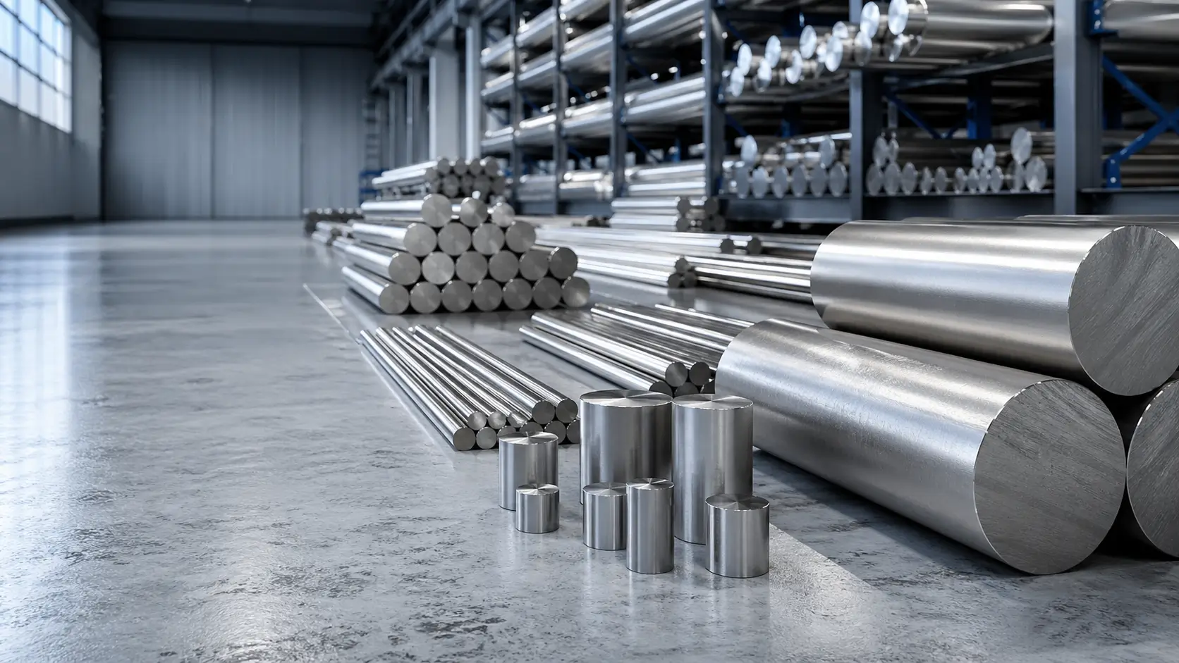
This is the table that doesn’t exist anywhere else in a single location. Parameters below are sourced from Carpenter Technology data sheets (CP Grade 4 and Ti-6Al-4V ELI), the Kennametal KSEM catalog (ISO S material group), Machining Doctor’s Ti-6Al-4V material data sheet, and the HonTitan machining guide for Grade 9. Use these as starting points — your actual optimal parameters will shift based on machine rigidity, coolant delivery pressure, drill geometry, and hole depth-to-diameter ratio.
Drilling Parameter Table by Alloy
| Alloy | Grade / Spec | Tool Material | Cutting Speed (SFM) | Cutting Speed (m/min) | Feed Rate (IPR) | Feed Rate (mm/rev) | Machinability |
|---|---|---|---|---|---|---|---|
| CP Titanium Grade 1–2 | ASTM B265 Gr.1/2 | HSS (M-7, M-10) | 50–80 | 15–24 | 0.002–0.005 | 0.05–0.13 | Gr.1: ~46%; Gr.2: ~40% |
| CP Titanium Grade 1–2 | ASTM B265 Gr.1/2 | Carbide (C-2) | 80–130 | 24–40 | 0.003–0.006 | 0.08–0.15 | Gr.1: ~46%; Gr.2: ~40% |
| CP Titanium Grade 3–4 | ASTM B265 Gr.3/4 | HSS (M-7, M-10) | 40–55 | 12–17 | 0.002–0.012* | 0.05–0.30* | Gr.3: ~35%; Gr.4: ~28% |
| CP Titanium Grade 3–4 | ASTM B265 Gr.3/4 | Carbide (C-2) | 60–100 | 18–30 | 0.003–0.008 | 0.08–0.20 | Gr.3: ~35%; Gr.4: ~28% |
| Ti-3Al-2.5V | Grade 9 / AMS 4943 | Carbide | 100–200 | 30–60 | 0.002–0.006 | 0.05–0.15 | ~28% |
| Ti-6Al-4V | Grade 5 / AMS 4928 | HSS (T-15, M-42) | 30–35 annealed; 25–30 aged | 9–11 | 0.003–0.012* | 0.08–0.30* | ~20% |
| Ti-6Al-4V | Grade 5 / AMS 4928 | Solid carbide | 160–230 | 50–70 | 0.004–0.010 | 0.10–0.25 | ~20% |
| Ti-6Al-4V ELI | Grade 23 / AMS 4956 | Solid carbide | 160–230 | 50–70 | 0.003–0.010 | 0.08–0.25 | ~22–24% |
| Ti-6Al-2Sn-4Zr-2Mo | Ti-6242 | Solid carbide | 98–164 | 30–50 | 0.003–0.007 | 0.08–0.18 | ~24% |
| Ti-5Al-5Mo-5V-3Cr | Ti-5553 (near-beta) | Solid carbide | 65–115 | 20–35 | 0.002–0.005 | 0.05–0.13 | ~15% |
*Feed rate for HSS drilling of CP Grade 4 and Ti-6Al-4V is diameter-dependent per Carpenter Technology: 0.001–0.002 IPR for 1/16″–1/8″; 0.004–0.010 IPR for 1/4″–1″; 0.012–0.025 IPR for 1-1/2″–2″. Feed rate scales with drill diameter to maintain proper chip load.
How to Read This Table
A few important caveats before you punch these numbers into your control:
The 10% speed rule. In titanium, a 10% speed increase above the recommended range reduces tool life by 30–50% due to the steep Taylor tool-life relationship. If you’re at the top of the range and getting short tool life, drop speed 10–15% before adjusting anything else.
Feed rate floors matter more than ceilings. The bottom end of the feed range is the danger zone, not the top. Running at 0.002 IPR when your drill diameter warrants 0.005 IPR is how you create work hardening. When in doubt, err toward the higher end of the feed range — you’ll get better tool life, not worse.
HSS vs. carbide breakeven. For job shop applications producing fewer than 20–30 holes in a run, HSS or cobalt-HSS drills are cost-effective and forgiving of variable machine rigidity. For production runs of 50+ holes, the speed advantage of carbide (3–5× faster than HSS) pays for itself quickly, and through-coolant carbide drills produce more consistent holes. The HSS speeds above are verified from Carpenter Technology’s machining guide — if your HSS is achieving those speeds without chattering, your setup is correct.
Grade 9 surprise. Ti-3Al-2.5V (Grade 9) machines 15–20% faster than Grade 5 at equivalent setups. Thermal conductivity is slightly higher (8.3 W/m·K vs. 6.7 W/m·K for Grade 5), and the microstructure is somewhat more machinable (~28% vs ~20% machinability rating against free-cutting steel baseline). Many shops default to Grade 5 parameters for all titanium alloys — that’s leaving productivity on the table when running Grade 9 tubing and hydraulic fittings common in aircraft.
Drill Geometry That Actually Works in Titanium
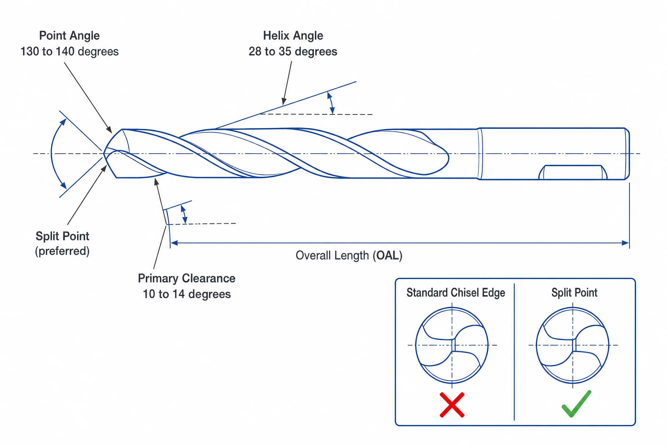
Titanium punishes the wrong geometry more than almost any other material. A point angle that would work fine in steel will cause drill walking and work hardening in titanium. Here’s what the geometry should look like and why.
Geometry Specification Table
| Parameter | Recommended Range | Notes |
|---|---|---|
| Point angle | 130°–140° | Split-point or web-thinned; reduce chisel edge to minimize thrust |
| Helix angle | 28°–35° | High-helix (35°+) for holes deeper than 3×D |
| Primary clearance (relief) | 10°–14° | Critical — insufficient clearance causes rubbing on work-hardened wall |
| Secondary clearance | 15°–20° | — |
| Rake angle | 10°–15° for finishing; 5°–10° for roughing | Positive rake reduces cutting force and heat |
| Chisel edge | Thinned / split-point | Standard chisel edge creates excessive thrust force; eliminates self-centering |
Point angle: The NAS 907 drill standard (used in aerospace titanium drilling, documented in DTIC report AD0620508) specifies 118°±5° for portable hand drilling and 133°–135° for fixed-feed CNC applications. Modern production practice has largely settled on 130°–140° for CNC drilling of titanium alloys, with a split-point or web thinning operation. The larger point angle reduces the axial thrust force that tries to push the drill out of the chuck, and the split point eliminates the dead chisel zone that generates heat without cutting at the center of the drill.
Helix angle: A 28°–35° helix is the production standard. Higher helix angles (35°+) improve chip evacuation in deep holes by increasing the helix pitch and reducing the distance chips travel up the flute. For hole depths beyond 3×D in titanium, switch to a parabolic-flute or high-helix design — they dramatically reduce the chip packing that causes drill breakage. The DTIC titanium drilling report specifies 29° helix for standard-duty titanium drills; most modern carbide offerings are in the 30°–35° range.
Clearance angle: This is the most commonly under-specified parameter. The clearance angle must be large enough that the flank of the drill does not rub against the work-hardened bore wall. Too little clearance (below 8°) and the drill burnishes the hole instead of cutting it — generating heat, causing chatter, and progressively hardening the wall. The DTIC specification calls for 10°–14° primary relief for NAS 907 Type C and B drills; anything less than 10° is trouble in titanium.
Coating: Why TiN Is the Wrong Choice for Titanium
This point is worth an explicit section because TiN-coated drills are still sold and used on titanium workpieces in shops that haven’t heard otherwise.
TiN (Titanium Nitride) is contraindicated for drilling titanium workpieces. Two reasons:
- Chemical affinity: The titanium in the TiN coating has strong chemical bonding affinity with the titanium workpiece. At the elevated temperatures of titanium drilling (900°C+ at the interface), titanium-to-titanium adhesion causes the coating to bond to the workpiece material, pulling coating fragments off the drill face and accelerating wear. This is the same mechanism as built-up edge but at the coating layer.
- Thermal stability: TiN oxidizes at approximately 550°C. The cutting interface in Ti-6Al-4V drilling regularly exceeds 900°C. Above its oxidation temperature, TiN breaks down rather than protecting the substrate. You’re running a coating that fails at 60% of the temperature it needs to withstand.
Correct Coating Options
| Coating | Oxidation Temp | Hardness (HV) | Notes |
|---|---|---|---|
| TiN | ~550°C | ~2,300 | Do not use on titanium workpieces |
| TiAlN | ~700°C | 2,800–3,300 | Forms Al₂O₃ thermal barrier layer; most common production coating for titanium |
| AlTiN | ~800–900°C | 4,000–4,500 | Higher Al:Ti ratio = better thermal barrier; preferred for aggressive cuts and higher speeds |
| Uncoated carbide | N/A | — | Sharp, thin edge; preferred at low speeds (<50 m/min); Sandvik recommends uncoated H13A grade for titanium stacks |
In practice: TiAlN is the workhorse coating for titanium production drilling — it’s what Kennametal, Guhring, and Sandvik use on their titanium-specific drill lines. AlTiN makes sense at the higher end of the carbide speed range (200+ SFM) where the additional thermal stability provides measurable tool life improvement. Uncoated carbide occasionally outperforms coated tools at very low speeds because the sharper cutting edge (no coating thickness on the edge) reduces the force required to initiate a cut — Sandvik recommends their uncoated H13A grade specifically for titanium-CFRP stacks.
Coolant Strategy for Titanium Drilling
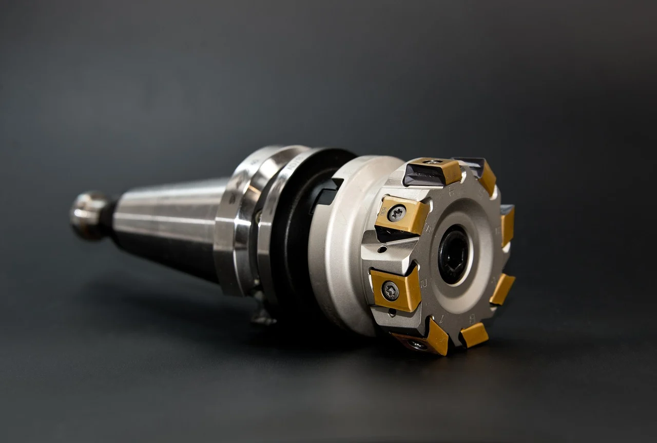
The number most shops get wrong on titanium coolant is not the fluid type — it’s the pressure. Most general-purpose machining centers deliver coolant at 150–400 PSI. That range is adequate for aluminum and steel but fails titanium at speeds above about 100 SFM.
The 1,000 PSI Threshold
At the cutting interface in titanium drilling, temperatures routinely exceed 500°C even at conservative speeds. At those temperatures, the coolant that reaches the cutting zone immediately vaporizes — forming a steam barrier that prevents liquid coolant from contacting the tool or workpiece. The vapor jacket insulates the cutting edge from the cooling fluid just as effectively as no coolant at all.
CTE Magazine documented the physical threshold: approximately 1,000 PSI (70 bar) of coolant delivery pressure is required to penetrate the vapor film at the cutting interface and make liquid contact with the cutting zone. Below that threshold, you’re delivering coolant that evaporates before it touches the drill tip.
Sandvik Coromant’s technical drilling guide recommends “high pressure up to 70 bar (~1,015 PSI)” as the standard specification for titanium and HRSA drilling. Their CoroDrill 860 system is rated to 80 bar (1,160 PSI). That is not marketing language — it is the physical requirement.
What this means practically:
- Shops running a standard CNC machining center without a high-pressure coolant upgrade (HPU) are limited to shallower holes and lower cutting speeds in titanium
- For holes up to 2×D at 100–150 SFM, 400–600 PSI flood coolant can work if delivery is well-aimed at the flute entry
- For holes 3×D and deeper, or cutting speeds above 150 SFM, high-pressure through-tool coolant (800–1,000+ PSI) is not optional
Through-Coolant vs. Flood Coolant
| Delivery Method | Appropriate Depth | Pressure | Notes |
|---|---|---|---|
| Flood coolant (external) | Up to 2×D | 400–600 PSI minimum | Chips must be evacuated by geometry alone; useful for short holes |
| Through-tool coolant | 3×D and beyond | 800–1,000+ PSI | Preferred for all production titanium drilling; delivers coolant directly to cutting edge |
| Dry drilling | Never | — | Not recommended for any titanium alloy at any depth; Sandvik explicitly states “never recommended for ISO S materials” |
Coolant Chemistry: The Chlorine Problem
This is the guidance that almost nobody publishes. Chlorinated cutting fluids must not be used on titanium. Chlorine-based extreme-pressure (EP) additives — common in older sulfochlorinated cutting oils — cause stress corrosion cracking (SCC) in titanium alloys, particularly in parts that will see stress in service. This is most critical for aerospace structural titanium (Ti-6Al-4V, Ti-6242) where a microscopic SCC crack initiated during machining can grow under service loading.
The approved coolant categories for titanium drilling:
- Semi-synthetic and synthetic water-soluble fluids (10%+ concentration) — most modern general-purpose coolants are chlorine-free and safe
- Sulfurized fatty cutting oils (not sulfochlorinated) — for slow-speed drilling with HSS
- Neat oils without chlorine EP additives — verify the SDS/TDS from your coolant supplier
Check your coolant supplier’s data sheet for “chlorine-free” or look at the EP additive section. If it lists “chlorinated EP additives” or “chlorinated paraffin,” do not use it on titanium.
Peck Drilling Titanium: G83 vs. G73 and Progressive Depth Strategy
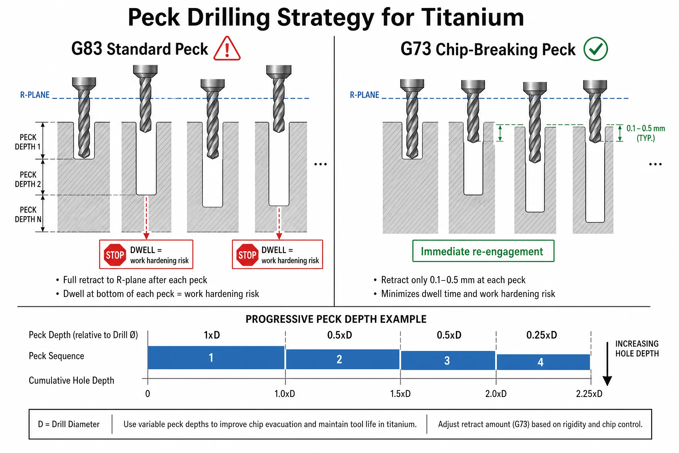
Peck drilling in titanium is mandatory for holes deeper than about 2×D — but the standard approach that works fine in steel actively causes problems in titanium. The issue is the dwell at the bottom of each peck.
The G83 Dwell Problem
G83 (deep-hole peck drilling cycle, full retract) is the default cycle on most Fanuc-compatible CNC controls. The cycle includes an optional P-word (dwell time in milliseconds at the peck depth). Many programmers leave a dwell in — sometimes copied from a steel program, sometimes because “it helps the chips clear.”
In titanium, that dwell is exactly wrong. At zero feed rate, the rotating drill contacts the work surface for the dwell duration — frictional rubbing, no chip formation, pure heat. By the time the drill retracts and re-engages, the bottom of the peck has already begun to work-harden. The next peck cuts a harder surface than the original material.
Fix for G83: Set P=0 (zero dwell) or simply omit the P-word from your G83 cycle. The retract and re-engagement should be immediate.
G73: Chip-Breaking Cycle (Preferred for Titanium)
G73 (chip-breaking high-speed peck) performs a very short retract at each peck depth — the distance is set by the machine parameter (Fanuc parameter 5114), typically 0.1–0.5 mm rather than a full clearance retract. This snaps the chip without fully clearing it from the hole — faster than G83, and critically, there is no dwell at the peck depth. The tool immediately re-engages.
For holes up to 8×D in titanium, G73 is generally preferred over G83. For very deep holes (10×D+) where chip evacuation requires full retract, use G83 with P=0 and rely on through-coolant to flush chips.
Progressive Peck Depth Table
| Peck # | Depth Increment | Notes |
|---|---|---|
| First peck | 1× drill diameter | Full diameter to establish chip groove |
| Pecks 2–5 | 0.5× drill diameter | Maintain chip load without heat buildup |
| Pecks near bottom | 0.25× drill diameter | Conservative depth as breakthrough risk increases |
| Any peck | 0 dwell | Never dwell at peck depth |
Starting depth for peck drilling: Most applications begin pecking at 2×D in titanium. For very aggressive carbide setups with excellent coolant delivery, some shops run to 3×D before switching to peck cycles — but 2×D is the safe starting point.
Chip appearance check: At each retract cycle on the first hole of a new setup, look at the chips. Titanium chips should be short curled ribbons (2–4 mm), slightly blue from heat exposure. Powder or dust means you’re rubbing rather than cutting. Long stringy chips mean your feed is too low relative to speed — increase feed.
Troubleshooting Common Titanium Drilling Problems
If something is going wrong in titanium drilling, the symptom almost always traces back to one of five root causes: speed too high, feed too low, coolant inadequate, tool geometry wrong, or tool worn. This table covers the most common shop-floor scenarios.
| Symptom | Likely Cause | Corrective Action |
|---|---|---|
| Drill breaks mid-hole | Feed too low (rubbing not cutting); chip packing; work-hardened surface from prior pass | Increase feed rate; check peck depth; verify dwell=0; check drill for wear before re-entering hole |
| Holes consistently oversized | Thermal expansion of drill; work-hardened wall pushing drill outward | Reduce cutting speed 10–15%; increase coolant pressure; change drill sooner |
| Short tool life (below expected) | Speed too high; coolant pressure insufficient; wrong coating (TiN) | Verify SFM against alloy table; confirm through-coolant at 800+ PSI; switch to TiAlN or AlTiN coating |
| Blue/black tint on drill flutes | Heat accumulation — cutting interface temperature too high | Reduce cutting speed; increase coolant pressure; shorten peck interval |
| Chatter when drilling | Insufficient feed (drill skipping instead of cutting); poor workholding rigidity | Increase feed; verify workpiece is clamped securely; check drill runout (max 0.002″ TIR for titanium) |
| Built-up edge (BUE) on drill tip | TiN coating (chemical affinity); speed too high; worn edge | Switch coating to TiAlN/AlTiN or uncoated carbide; verify cutting speed; replace drill |
| Reamer chatters after drilling | Work-hardened bore from drilling | Root-cause the drilling step: check feed rate, dwell, and tool wear before the reaming pass |
| Tapping torque spikes | Work-hardened drilled surface from poor drilling parameters | Same as above — fix the drilling step, not the tapping step |
| Hole entrance burr excessive | Point angle too small; feed too high at entry | Reduce feed 50% for first 2× diameter at entry; chamfer entry or use spot drill first |
| Hole exit delamination (in Ti stacks) | Feed not reduced at breakthrough | Reduce feed to 50% starting 1 drill diameter before breakthrough |
Thin-Wall and CFRP-Titanium Stack Drilling
Titanium frequently appears in aerospace assemblies as thin-walled components (0.5–3 mm wall thickness) or in CFRP-titanium stacks where carbon fiber and titanium layers are drilled in a single operation. Both scenarios require parameter adjustments beyond the standard guidelines above.
Thin-Wall Titanium
Problem: Thin walls flex under drilling thrust force, causing chatter, hole bell-mouthing, and delamination on the exit side.
Adjustments:
- Reduce feed by 30–50% compared to the alloy table values
- Use a spot drill or center drill to establish a positive starting point before drilling
- Use a backup block (rigid backing plate) on the exit face to prevent material lifting
- Pilot drill to 50–60% of final diameter before finishing — reduces thrust on the thin wall
- Increase spindle speed slightly to compensate for lower feed (maintain chip load by increasing SFM 10–15%)
CFRP-Titanium Stack Drilling (Aerospace)
This is one of the most demanding drilling applications in aerospace manufacturing. The two materials have conflicting requirements: CFRP needs high speed and low feed to avoid fiber pullout and delamination; titanium needs low speed and high feed to avoid work hardening and tool adhesion.
Parameter compromise for CFRP-Ti stacks (from Sandvik CoroDrill 452 and CoroDrill 863 application guidance):
| Layer | Speed (SFM) | Feed (IPR) | Notes |
|---|---|---|---|
| CFRP entry | 500–700 | 0.001–0.003 | Low feed to prevent fiber pullout |
| Transition zone | Reduce speed before Ti entry | 0.003–0.005 | Slow down before hitting titanium |
| Titanium layer | 130–200 | 0.004–0.008 | Compromise speed; uncoated carbide preferred |
| Exit through CFRP | 500–700 | 0.001–0.002 | Reduce feed again at exit |
Coolant note: Sandvik recommends their uncoated H13A carbide grade for titanium-CFRP stacks specifically because the sharper cutting edge (no coating thickness) minimizes burr formation at the CFRP layer interfaces and reduces the adhesion tendency on the titanium layer.
Backup plates: Rigid backup plates are mandatory on the CFRP exit face. Without backing, the last layer of carbon fiber delaminates at breakthrough.
Recommended Carbide Drill Lines for Titanium
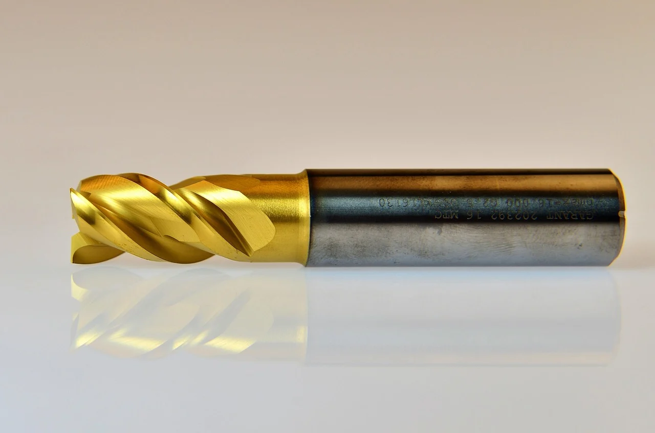
You don’t need a titanium-specific drill to start — the speeds and feeds above apply to any solid carbide drill with the right geometry. But if you’re running a production titanium job (50+ holes per run), these manufacturer-specific lines have geometry and coatings dialed in for the material.
Kennametal KSEM Modular Drill
Modular system covering 12.5–101.6 mm diameter with replaceable carbide insert blades. The ISO S material group (titanium, HRSA) grade is KC7315 — a TiAlN-based PVD multilayer coating on ultra-fine grain carbide substrate. Recommended parameters for ISO S group: 50–80 m/min (165–260 SFM), 0.09–0.20 mm/rev depending on diameter. The modular design allows blade changes rather than full drill replacement, which matters in large-diameter titanium applications where each drill costs significantly more than a small solid carbide.
Sandvik Coromant CoroDrill 860-SM
Solid carbide drill, 3–16 mm diameter, with the “-SM” geometry variant specifically for titanium (ISO S material). Features internal coolant channels, corner reinforcement for reduced chipping at the outer corner, and an optimized double margin for bore wall stability. Achieves H8–H9 hole tolerance without reaming in stable setups. Through-coolant at 70–80 bar (1,015–1,160 PSI) is the design specification.
Guhring RT 100 T (Series 6513)
Deep-hole titanium and stainless steel drill, capable to 30×D. TiAlN coating, 135° point angle, through-coolant standard. Designed specifically for deep-hole drilling in ISO S and M materials where chip evacuation is the primary challenge. The 30×D capability is exceptional — most competitors top out at 10×D for titanium-specific solid carbide designs.
Guhring RT 100 US (Series 5741)
Standard-depth (3×D) titanium and stainless drill with Guhring’s nano-A coating (a nano-structured AlTiN variant with ~4,500 HV hardness). 140° point angle, no through-coolant (external flood application). The nano-A coating provides excellent thermal protection without the edge-radius penalty of thicker PVD coatings.
Mikron Tool PDC and ADC Series
Mikron’s titanium-specific micro-drill lines (1–6.35 mm diameter) with two geometry variants: PDC for commercially pure titanium grades (documented at 45 m/min, 0.030 mm/rev in CP Grade 4 with 2,200-hole tool life on medical bone plates), and ADC for titanium alloys including Grade 5 (60 m/min, 0.020 mm/rev). These are the relevant choice for medical device and precision aerospace applications where hole diameter is below 6.35 mm.
Frequently Asked Questions
What cutting speed should I use to drill titanium?
It depends on the alloy and tool material. For Ti-6Al-4V (Grade 5) with solid carbide, 160–230 SFM (50–70 m/min) is the standard range. For commercially pure titanium (Grade 1–2) with carbide, 80–130 SFM is appropriate. HSS drilling is significantly slower — 30–55 SFM depending on alloy. Always pair the speed with an adequate feed rate; slow feed at slow speed causes work hardening.
Why does titanium work harden when drilling?
Work hardening in titanium drilling is a process outcome, not a material inevitability. It occurs when the drill dwells, rubs, or cuts at too low a chip load. Titanium’s hexagonal close-packed crystal structure has limited dislocation slip systems — when the near-surface layer is plastically deformed without adequate chip formation, those dislocations pile up and harden the surface. The root causes are: insufficient feed rate, dwell in peck cycles (G83 P-dwell), and using a worn drill past its useful life.
Can I use TiN-coated drills on titanium?
No. TiN (Titanium Nitride) coating is contraindicated for drilling titanium workpieces. The titanium content in TiN has chemical affinity with the titanium workpiece at cutting temperatures (900°C+), causing the coating to bond to the workpiece material and accelerating wear. TiN also oxidizes at ~550°C — below the 900°C+ interface temperatures common in Ti-6Al-4V drilling. Use TiAlN (oxidizes at ~700°C) or AlTiN (800–900°C) coated carbide instead.
How much coolant pressure do I need when drilling titanium?
At least 1,000 PSI (70 bar) for through-tool coolant delivery in production titanium drilling. At drilling temperatures, coolant vaporizes before reaching the cutting interface unless sufficient pressure is present to penetrate the vapor layer. Standard machining center coolant (150–400 PSI) is adequate only for very shallow holes (under 2×D) at lower cutting speeds. Sandvik’s standard specification is 70 bar for titanium and HRSA drilling.
Can I drill titanium without coolant?
No, for any production application. Dry drilling titanium results in extremely short tool life, work hardening, BUE formation, and thermal damage to the workpiece. Sandvik explicitly states that dry drilling is “never recommended” for ISO S materials (titanium, HRSA). At minimum, use a flood coolant application; through-tool coolant at 800–1,000+ PSI is the production standard.
What’s the difference between drilling CP titanium and Ti-6Al-4V?
Commercially pure titanium (Grades 1–4) is significantly more machinable than Ti-6Al-4V — roughly 45–55% machinability vs. 20% for Grade 5. You can run carbide speeds 30–80% faster on CP grades than on Grade 5 (80–130 SFM vs. 160–230 SFM). CP titanium also requires lower coolant pressure for equivalent hole quality. Grade 5 is the challenging alloy; CP grades are closer to drilling austenitic stainless steel in difficulty.
Why does my drill keep breaking in titanium?
Most drill breakage in titanium traces to one of four causes: (1) feed rate too low — the drill is rubbing rather than cutting, generating work hardening that requires progressively more force; (2) G83 dwell active — pausing at peck depth causes work hardening at the bottom of each peck; (3) chip packing in the flutes from insufficient coolant pressure or too deep a peck increment; (4) wrong coating — TiN chemically bonds to titanium and causes built-up edge that eventually chips the cutting edge.
When should I start using peck drilling in titanium?
Begin peck cycles at 2×D depth in titanium. Use G73 (short retract, chip-breaking) rather than G83 (full retract) where possible to minimize cycle time and eliminate the dwell risk. Set peck increments at 1×D for the first peck, 0.5×D for subsequent pecks, and 0.25×D for the final pecks near breakthrough. Never use a P-dwell in G83 on titanium.
My Take: The Five Things That Actually Matter in Titanium Drilling
After reviewing Carpenter Technology’s machining data, Kennametal and Sandvik’s production application guides, and the peer-reviewed literature on titanium drilling, a clear pattern emerges. Shops that succeed with titanium drilling share five practices; shops that struggle usually violate at least one.
1. Feed rate is the most important parameter, not speed. Everyone fixates on cutting speed because speed is what makes tools break catastrophically. But feed rate is what determines whether you generate chips or generate heat. Keep feed at the middle-to-upper range of the alloy table. Low feed at low speed is the wrong combination — it just slowly cooks the drill and hardens the hole.
2. Coolant pressure, not coolant volume. If your machine can’t deliver 800+ PSI through the tool, your drilling performance will plateau regardless of what drill you buy. A high-pressure coolant upgrade (HPU) on a standard machining center is usually the highest-ROI tooling investment for a shop adding titanium work.
3. Zero dwell in your peck cycle. Pull up your G83 programs and remove every P-word from the titanium jobs. This one change prevents a large percentage of drill breakage in titanium peck drilling.
4. Tool life is shorter than you think. In Ti-6Al-4V, plan for drill change intervals around 40–60 holes for a solid carbide drill in a production setup. The first sign of trouble — a load spike, an oversized hole — means the drill crossed the 0.3 mm flank wear threshold. Build in a change before that point.
5. TiN is wrong for titanium. Check your crib. If you have TiN-coated drills designated for titanium work, replace them with TiAlN or AlTiN coated equivalents. The chemical mechanism is fundamental — no amount of speed or feed adjustment compensates for running the wrong coating.